I have been waiting
for a long time to get a front locker... and now it is here!! I
looked at what was available for the Tacoma, and decided on the ARB.
ARB recently updated the Air Locker... Here is what 4x4wire.com
had to say:
"This ARB unit
is their latest in design. It is a new timed-gear Air Locker which has
its side-gears and spider gears clocked (timed) from the factory to
provide a perfect distribution of the load over all teeth when the Air
Locker is locked. The resulting strength increase in some applications
has approached 300%. In basing the RD90 on their timed-gear design,
changes were also made to the way the air is delivered. Traditional
Air Lockers receive their air at the bearing opposite the ring-gear.
The timed-gear Air Lockers receive their air at the bearing on the ring-gear
side. This means that on the IFS Toyota the air line enters on the small
side of the split case. In addition to this change, the timed-gear Air
Locker also benefits from a two-piece case instead of the traditional
three-piece design and they have eliminated the need for the annular
piston used to transmit the air's force to the locking clutch-ring.
In a nutshell, the RD90 is stronger, simpler in design and easier to
install than a traditional Air Locker."
The install was
going to happen over a few days. First I was going to put
the compressor and switches in. Next we were going to pull
the front out and install the locker.
|
|
|
Here
is a exploded view of the RD-90
|
|
|
And
this is a animated view of how it all works.... you can see the air actuated
piece slide over and lock the differential.
|
|
|
Here
it is!! I cant wait to get it installed!!
|
|
|
My
first job was to mount the compressor. I looked around for
a spot to mount it, but I was concerend about a few things. I
could mount it under the truck on the frame somewhere, or under the ARB
front bumper, but I was worried about extreme dust, water and mud. I
finally figured out where I was going to mount it: on the firewall next
to the wiper motor.
|
|
|
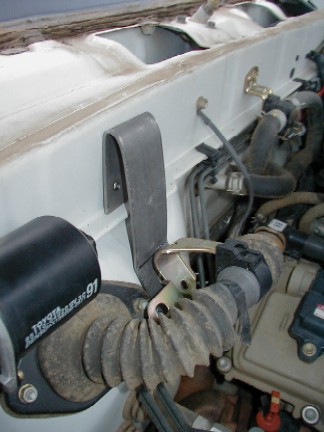
I
started working on a bracket. The bracket is going to bolt with
three bolts and a backing plate to the firewall on top, then also mount
with one screw on the bottom. The bottom screw will be shared
with a bracket that supports the wiring harness as it passes through the
firewall, that is the large accordian tube seen in this picture. I
bent the harness bracket down slightly to make it fit better.
|
|
|
I
had to remove the plastic screen at the bottom of the windshield to gain
access to the back of the firewall. You have to remove the wiper
arms to get it off.
|
|
|
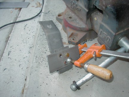
Next,
I shaped the bracket. I then clamped the backing plate to the bracket
so the holes would line up.
|
|
|
The
ARB compressor mount and backing plate will mount "around" the
bracket. I will also give the ARB backing plate a little weld to
hold it in place.
|
|
|
Here
is an initial test fit to see if everything will clear. There is
plenty of room all around.
|
|
|
The
next thing to do was to mark and drill the holes for the bracket.
|
|
|
After
drilling the holes, I gave the bracket and backing plate a coat of paint
to help with rust.
|
|
|
The
hardest part of mounting and wiring the compressor by far was getting
the backing plate and bracket attached!
|
|
|
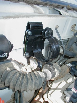
Here
you can see the bolts going through the backing plate, firewall, and mounting
bracket. The large arm is the windshield wiper arm.
|
|
|
Once
the bracket was on and tight, I put the compressor bracket on. I
used the ARB hardware with lockwashers, but I also added some locktite
to make sure they dont come loose.
|
|
|
Here
you can see the compressor in.
|
|
|
I
then attached the soleniod and pressure switch. I used some Rector
Seal to make sure there are no leaks.
|
|
|
The
compressor was then tightened into the bracket and wired.
|
|
|
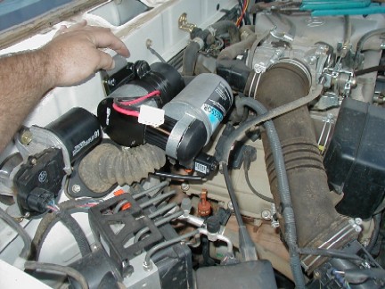
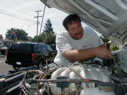
My
daughter was playing with the camera and took a picture of me putting
the compressor in.
|
|
|
Next
I had to cut a hole for the alarm panel to mount in. It can
be rough around the edges, as the panel covers them up.
|
|
|
The
ARB switchs did not just go into the front holes of the panel, the holes
needed to be enlarged. With my steady hand, I made a slight bo-bo
between the switches as you can see in these pictures.
|
|
|
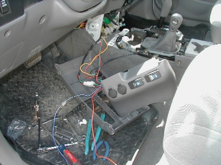
Here
is the panel with all the switches and alarm panel installed.
|
|
|
I hooked up the
wires and tested the system. It worked good, so now it was
time to put it back together.
I added some glue
to the back of the switches to make sure that they stay put.
|
|
|
Here the inside
is all put back together.
I did cheat on one
thing: the instructions call for two wires, one to be hooked up to a
keyed power source (one that is on only with the ignition switch), and
one to be connected to a dash light circut. I put both wires
to the keyed circut. This means that like my tilt meter,
(the wire I tapped into) when the ignition is on, the switches will
be lit up.
|
|
|
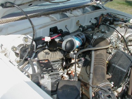
Here
is what it now looks like under the hood. All that is left
is to attach the air line to the front diff..
|
|
|
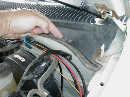
One thing that I
will have to get is two of these plastic snaps. Like most
of these parts, they dont always work a second time. There
are four of them and 6 screws that hold the plastic across the bottom
of the windshield, two worked a second time, two did not.
The part number
for them at Toyota is:
|
|
|
The next step was
to remove the differential. This was way easier that I thought
it would be.
Raise and support
the vehicle, remove the front tires.
Drain the front diff fluid.
Disconnect the front drive shaft at the front diff..
|
|
|
Remove
the 4 bolts that attach the lower ball joint to the lower arm. In
this picture you can see 3 of the 4 bolt holes.
|
|
|
Once
the bolts are out, you can lift up on the suspension and swing it out.
Using a large screwdriver or pry, "pop" the inner
axle stubs out of the differential.
|
|
|
You then neex to
remove the two bolts in front of the diff, shown with arrows here, and
on hex nut from under the crossmember (this hex nut requires a 12mm
allen key). Disconnect the electrical connector, one vaccum
line, and the front diff breather (the front diff breather will disconnect
it self if you cant reach it!). There are is also one wiring
harness that you need to remove (12mm bolt), and one that snaps off
with a plastic peg.
You can now pull
the front suspension out to completely remove the cv stubs, and then
the diff drops right out!
This was the first
time I did it, and it only took about 30 minutes to do! Going
back in will take more time, as you will want to put loctite on the
ball joint bolts, and on the front drive shaft bolts.
|
|
|
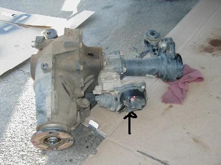
Here
it is out of the truck. The arrow shows where the wiring plug and
the vaccum line go. You can see the breather located more towards
the top of the diff.
|
|
|
We
removed the ADD section and set it aside.
|
|
|
We split the "clamshell"
case and removed the carrier. Unlike normal differentials,
there are no races and bearings to unbolt like the common differential.
The case has the races in each side and so when you split
it the carrier comer right out.
Here is the stock
unit and the ARB unit.
|
|
|
We
removed the bearing we were going to use again and cleaned it.
|
|
|
We
did not have the correct size tool to press the bearing onto the ARB unit,
but Eric always has a trick up his sleeve... In this case,
he just made one!
|
|
|
Next we shimmed
and installed the bearing on the ARB unit.
The ARB instructions
explain the whole shimming process and the kit includes some extra shimms
so you can get the correct bearing pre-load.
|
|
|
Here
is the ring gear and the ADD stub that goes into the carrier. The
teeth on the large end of the ADD stub are where the axle locks and unlocks.
|
|
|
We did a loose fit
of the ring gear. It would not quite fit, but Eric
has the perfect solution for ring gears also... a pizza oven that they
fit into just right!
Once it was warmed
up it went right on.
|
|
|
We
drilled the hole in the shallow half of the case for the air line.
|
|
|
Here
you can see more detail on where the hole goes. Again, the
ARB instructions are really good and specify where to drill the hole. There
are some stamped markings in the case that we refrenced from some pictures
of installed units.
|
|
|
We
did a loose fit to check the hole... without moving the tube it was almost
exactly perfect.
|
|
|
We
tapped the hole and installed the fitting.
|
|
|
After
we thought everything was good with the shimms we ran a check pattern
just to be sure. It came out looking great so we got ready
for the final assembly.
|
|
|
Because
we had already fitted the case and checked everything and this was the
final assembly, we installed the two "O" rings into the assembly.
It is important that you dont install them until the final
fit so they dont get damaged.
|
|
|
We
installed the ADD stub into the differential.
|
|
|
Next the ADD section
was put back on. Now it was time to put the diff back into
the truck!
We ran into one
little problem during this phase of the install... We had to remove
the bearing race on the deep side of the clam shell diff. to install
the required shimms, and to do so you have to remove the CV axle stub
oil seal. We could not remove it without damaging it, so
we had to get a new one for this side. If not for that, we
could have used both of the old ones again as the truck is new and has
low miles.
|
|
|
Once
the new seal was in, putting the diff back in the truck was a 15 minute
job.
|
|
|
When
you put the lower joints back together, be sure to use lots of lock tight!
|
|
|
By
this time, I was tired of working under the truck, so Kris (TRDLABS) and
I went to his shop and did a pre-Moab fluid change and finished connecting
the ARB air lines there.
|
|
|
Here
you can see the line going to the front differential.
|
|
|
To
help protect it more, we put a sleve of fuel line over the ARB air hose.
|
|
|
During
the process, we broke the breather nipple off the ADD unit. The red arrow
shows the location on my truck. Some of the older Tacomas
use Vaccum to operate the ADD unit, but mine is electric and runs off
the large electrical plug.
|
|
|
Here
is another shot of the broken nipple and the breather hose laying there.
I drilled the hole
out and glued a new nipple into the housing.
|
The
front locker works great! Also check out the install of the ARB
tire inflation kit HERE!
|
| Back
to the Tacoma Page |
|
Back
to the Home Page
|