We finally had the chance to install the Fabtech 6 inch lift. After finding someone that wanted to install one on their truck and MANY calls to Fabtech trying to get one in stock and shipped to us it arrived.
We set up a date and got the lift installed with only minor problems in about 19-20 hours total. This time included a few breaks for lunch and such, plus running to have the press work done and a few trips to the hardware store.
My overall first impressions of the kit: The kit appears to be plenty strong and the quality of the parts seem good. 95% of the parts went together without much problem, but there were a few parts that did not want to line up, mainly the impact struts that connect the rear cross member to the transmission cross member. I liked the much beefier and stronger new front knuckles, and the fact that they provided upper ball joints that you could add grease to. Instead of a spacer in the steering linkage, Fabtech used a new longer slip joint to attach the steering shaft to the rack.
For the rear, Fabtech used a add-a-leaf and block combination instead of just a big block like some other kits come with. A better yet solution may be a even smaller block and some new shackles. The only problem in the rear is that the shocks limited wheel travel, but without requiring further fabrication they did the best that they could with what they had to work with.
I was disappointed that we had to make 2 trips to the hardware store and one search through my parts bins for missing nuts and bolts. Although plugs for the ABS sensor holes were provided for non-ABS trucks the small bolts to hold them in place were not provided, warranting another rummage through my parts bins for the small bolts. While you did get about 6 inches of lift from the kit, overall the front wheel travel was decreased.
The instructions that came with the kit were not good. Fabtech should re-work the instructions with better descriptions, pictures, and re-order a few of the steps to prevent headaches.
For both the front and rear of the kit, Fabtech would have you add brackets and bend the factory brakes lines so that they will work with the kit. This is not a good method, and I highly recommend that you purchase separate longer brake lines and do the job right.
We will follow up on the kit after a few months and re-check the alignment and make sure that it is staying put.
All Pictures HERE.
For a copy of the instructions that were included with the lift click HERE.

Here are the contents of the 3 boxes.
Before you get started, I would suggest reading through the instructions to get an idea of what you will be doing.


During the install, I had plenty of chances to mess with Than:
Wow... this is messed up... You have done this before, right Pete?


This is the before shot of the truck. Than had sold his factory tires and wheels so he had to borrow some others to get him to the install. Because of this, the front tires were smaller and the truck was slightly nose down. This will affect the before and after measurements.
When we started, here were the measurements:
LF=14
RF=14.25
LR=16
RR=16.25
Where you measure from on the frame is not that important. Try to find spots front and rear that you can easily find to measure again afterwards. We are just looking to find out how many inches we gain.

The first step is to tear down the front end.
Raise and support the vehicle. Remove the wheels, brake caliper, rotors and strut assembly and set aside for later.
Do not let the brake calipers hang! Use a piece of wire or string and hang them so no pressure on the brake line.

The next step is to remove the factory knuckle. Remove the large center nut (yellow arrow), then separate the upper ball joint from the upper control arm (red arrow) . Remove the tie rod end from steering knuckle. Remove the sway bar ends from the lower control arms (green arrow).
It is helpful to have various pullers to help with the tie rod end and the upper ball joint!


At this point, this is about what your truck should look like.
The next step is to drain the front diff.


On the drivers side there are two bolts that hold the rack in place (yellow arrows) that will need to be removed. One is horizontal, the other is vertical.
Once the bolts are loose or off, just let the rack sit where it is, we will deal with it in a minute.

Remove the sway bar. The sway bar is held in place with two bolts on each side. The bolts are in pockets that are really fun to get to.
Once the sway bar is loose, remove it and set it aside for later.


Here is another shot of the two rack bolts on the drivers side (yellow arrows) again.
You will need to remove the large "nut" that is the rear mount for the front differential. The nut is inside a pocket of the rear cross member in the hole shown by the green arrow. It will require a 12mm allen key.

Remove all electrical, vacuum and breather connections to the front differential. There is one small bracket that holds the breather that is on top and uses a 10mm bolt that is hard to see, so check good!
Once all connections are loose, remove the two front mounting bolts and lift the front differential out of the truck. Take care not to break the small plastic breather nipple on the add housing!

Remove the steering coupler from the rack.
Take the rack out of its stock position and tie it up and out of the way. You do not need to remove any fluid lines.

Here you can see the rack tied up and out of the way.
Remove the 4 bolts (2 on each side) that hold the lower control arms in place. Be careful to put all the alignment cam hardware back the same way it came apart. I would suggest putting it back into the arms so you know where it all goes.


This is what the truck looks like at this point.
It is now time to start installing the lift!
According to the Fabtech instructions, this puts us just finishing with step 14.

At this time we decided to go ahead and have the press work done. It was a Friday and the show was going to be closed Sat-Mon so we wanted to get it out of the way.
I would suggest that you go to your local Toyota dealer and ask where they have their press work done. This will ensure that you have a shop that has done these before and is familiar with how it works.

The shop first presses the hubs out of the old knuckle and bearings. This process ruins the bearings.
Quite a bit of pressure is required to press the hub out. While it will vary from vehicle to vehicle, it took about 18 tons to press this hub out. When it moved, it did so with a bang.

The oil seal is installed on the new Fabtech knuckle.
Fabtech supplied the two outer seals, but one of ours was damaged during shipping. This is a Toyota item that most parts stores will not carry.


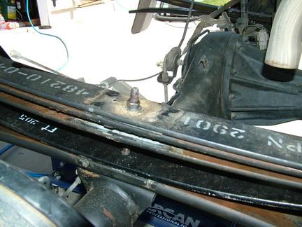
Now it was time to mark and cut the rear cross member!
The instructions call for cutting the rear cross member 1.5 inches from the cam pocket towards the center, making sure that you don't cut into the cam pocket itself.
Don't worry, there will be pictures in a minute!


This picture gives you a better idea of what they are talking about. They want 1.5 inches from the edge of the cam pocket (green line).
Next in step 15 they want you to measure up 2 inched into the pocket and cut diagonally. In this photo, we have made a black line to show about where this cut will be.


When we did the test fit, things were not cut far enough back, so off goes the cross member and some more cutting and grinding was in order.
It took 3 test fits before everything was clearing correctly.


Here is a shot of the drivers side after all the trimming was done.
In step 18 (for V-6 models) they want you to loosen the pressure line fitting and rotate it and then re-tighten it. Doing as they asked would have made us have to do more trimming so we left it the way it was.

Step 21:
We removed the factory steering shaft coupler and installed the new Fabtech supplied longer one.

At this point I decided to change out the factory strut springs to the new Fabtech struts.
To do this you need to have spring compressors. This is a step that if you have not done it before I would recommend that you take it to a shop and have it done. You can be seriously injured if you don't do things exactly right!

The spring needs to be compressed so that the top plate (green arrow) is loose and can be removed safely.
The larger nut in the center (red arrow) is what holds the top plate on. If this nut is removed and there is still pressure on the spring, it will explode apart and you will be injured!
The three smaller nuts (yellow arrows) are what hold the strut onto the vehicle.


Although its not the greatest picture, you can see the length difference between the factory strut left and Fabtech strut right.
What does this mean to you? With the Fabtech strut you will loose some wheel travel.

Here is a side by side shot of a factory strut and the assembled Fabtech strut.
Because the Fabtech strut is shorter, you will loose some wheel travel. It will also increase the stiffness of the front end some.


The lower control arms are installed.
This is where we found out that to install the bolts that the rack had to be moved out of the way.


With the lower control arms back into place, we noticed that the bump stops were not even. The front bump stop hits and the rear has some room still.
Because the bump stops are of different heights, we had a easy fix.


We did a rough fit and found that the bolt that holds the impact strut to the mount (yellow arrow) was going to be off by quite a bit. Instead of installing the mount then fighting with the bolt, we did things a little differently.
We installed the mount loosely, then installed the bolt. With everything in place, we tightened things up a little on each bolt at a time. This brought things into line and saved up a big fight.


I install the tops first hand tight then install the bottoms and torque everything down.
When you get to the bottom, if it is not lined up, don't worry.


The new knuckle is installed. I install the upper ball joint into the upper control arm hand tight then install the 4 lower bolts.
The lower bolts are given a shot of lock tight and torqued to 43 ft-pounds per the Fabtech instructions.


The sway bar can be re-installed and connected to the lower control arms again (yellow arrow).
The upper and lower ball joints can be tightened.
If the truck has ABS, you can install the ABS sensor into the hole (red arrow). If not, a plug is supplied to close the hole.
For our kit, they did not include the small bolts to hold the ABS plugs into place.

The rotors and calipers were re-installed.
The Fabtech instructions would have you relocate the brake line brackets and keep the factory front brake lines. We are not going there!
If you have enough money to lift your truck, spend the extra $75 on extended brake lines. The brakes are not a place to cheap out!
The large outer nut that holds the CV half shaft is installed and torqued (green arrow).


All the bolts in the front end are torqued down and double checked. There are a lot of bolts that we left loose, so now is the time to go back and make sure they are all tight!
If you follow the kit instructions, you would not have tightened all the bolts down as they have you leave them loose but never say to go back and tighten them!
The front wheels are installed.


Now its time for the rear.
Raise and support the rear. Remove the wheels and set them aside.


For the rear, I suggest doing one side at a time.
Using a jack, support the axle so that there is not any weight on the rear leaf springs either upward or downward (a neutral position.)
Remove the factory U-bolts, then loosen and remove the center bolt for the leaf springs. Once they are apart, SLOWLY lower the rear axle until you have room to insert the add-a-leaf.
I left the parking brake cable on at first to help steady the axle. It is not under much pressure and can still be easily removed.
To insert the new add-a-leaf I now had to disconnect the parking brake cable.
Insert the add-a-leaf and the new longer center bolt for the leaf springs. Use the jack to slightly raise the axle until you can get the nut started on the new center bolt.


Slowley lower the rear axle until you can insert the new block. The centering pin on the block will go into the pad on the axle, and the head of the leaf spring bolt will go into the hole on the block.
Install the new U-bolts.


Flip the parking brake cable.

Flipping the parking brake cable.
For more info on this step, click HERE.


Again Fabtech's instructions called for you to use brackets and bent the brake lines to use the stock rear hose. Again, we are not going there!
Install the new longer rear brake line!

Install the new rear shocks.
Install the wheels.
Check over both the front and rear for any loose bolts or anything else that you may have missed.
Bleed the brakes, you just installed new brake lines so there is a ton of air in there!

The after height measurements of the truck:
LF: 21.75 Gain of 7.75
RF 22 Gain of 7.75
LR: 21.5 Gain of 5.5
RR: 22 Gain of 5.75
Keep in mind that the front wheels were smaller than the rear when we started. I think that the actual front gain was in the area of 5.5 inches.
Go to the alignment shop!

The before and after alignment numbers.
We will follow up in a few months and see if the alignment is staying put.


Some flex shots.
In the rear, the shocks are a major limiting factor. While the 33x12.50-15 tires did not rub, there was room to play with.


6-30-2005